3D vision

3D vision
3D vision is an important cornerstone of modern industrial vision systems. Think of dimensional control, localisation and mapping, measuring deviations with a CAD model or bin picking. However, there are different technologies used to measure 3D images, and different methods to process and store 3D data. This article provides an introduction to 3D vision, the data sets, and the underlying technologies.
Introduction
A classic two-dimensional photograph shows a scene or object as observed from a single point. This is similar to what we would see if we were to view a still scene from stillness with one eye. In such an image, there is no information about depth, or distance of objects from the observer or camera. Contextual information can, however, give some qualitative hints about depth. If a picture contains a large laptop and small pine trees, one can assume that the trees are further away than the laptop. Similarly, occlusion indicates a sequence of objects in terms of depth. However, such qualitative contextual information is often not enough to make appropriate decisions, often requires a lot of computing power and is prone to errors.
However, many industrial applications benefit from detailed depth information. Examples include localising pallets in a department store, a robot locating and mapping an environment ("simultaneous localisation and mapping", or SLAM), picking objects from a box with a robot arm, or checking the position or dimensions of objects. 3D imaging can provide a solution here.
3D data sets
A 3D data set can be represented in different ways in a computer system, or perceived by vision hardware. The most common representations and their limitations are shown below.
Computer design
"Computer aided design" (CAD) is the use of computers to design, optimise and analyse a design. It is especially applicable for industrial objects, where an "ideal" design is developed digitally on a computer. A wide range of software for 3D CAD design is available, ranging from relatively simple to very advanced, from free to very expensive. Note that computer design also has applications in the entertainment industry, for example in video games or cartoons.
An "ideal" computer design usually consists of a combination or sequence of geometric operations, combining, adding and subtracting elementary geometric objects (cube, plane, cone, sphere, etc.) together. This is especially suitable for industrial objects, as organic shapes that are difficult to map onto elementary geometric shapes do not often occur here. Additionally, one can add information about the textures, materials or colours of surfaces and parts, and add lighting in the scene.
For practical use, such an ideal geometric design is often discretised. Many algorithms can only deal with lines, planes and/or discrete point representations, and the ideal CAD design is then discretised, often in the form of triangles sharing a rib each. Smaller triangles result in more polygons going into the discretised representation, a larger resulting file, and smaller discretisation errors. Triangulation is a complex subject in itself, with an extensive literature and software available.
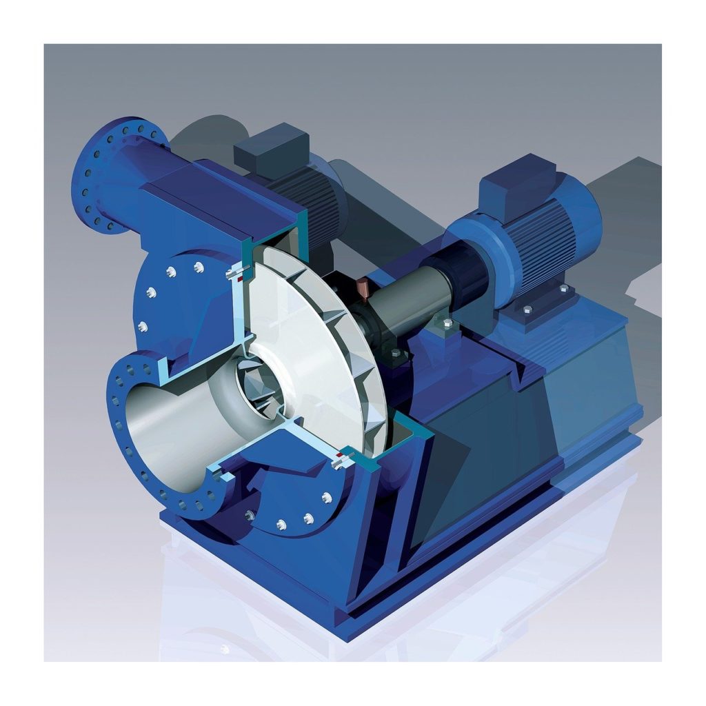
A CAD mechanical design, where all parts are represented as elementary geometric objects and operations.

A discretised CAD design of a head, with the ideal model reduced to a triangulation.
Point cloud
Another way of representing a 3D object in digital form is as a point cloud, consisting of a large number of points in 3D space located on the object's surface.
A point cloud of a torus. Lucas Vieira, Public domain, via Wikimedia Commons
The distribution of points over the object often determines the quality of the point cloud:
- If the number of points is too low, fine details of the 3D object will not be well represented
- The point cloud can be partial, e.g. only the front of the object is present and the back is not
- The distribution of samples over the surface can vary greatly and need not be anything but homogeneous.
Furthermore, there is also no relationship between the points present, and it is usually assumed that "neighbouring" points lie on the same surface. However, this need not be the case, which is certainly a problem for erratic shapes or complex shapes with holes or thin parts. For example, one can simply go from a triangulation to a point cloud by keeping only the vertices of the triangles as points, and removing all relations between them. The reverse path, however, is much more complex and not unambiguously defined.
However, a point cloud is often the output of 3D vision systems, so in practice we are often forced to work with it.
Depth map
A special type of point cloud is a depth map. A depth map can be represented as a monochromatic 2D photo (a 2D photo with only 1 channel), where the number in each pixel represents the distance in the scene. Another representation is that with from the focal point of the camera, a single line is created through each pixel in the photo, recording the distance to the corresponding object in the scene. In this way, a point cloud of the scene is obtained, with the following limitations:
- The entire scene is present, no distinction is made between different objects
- Only one side of each object is present. A full 3D representation cannot simply be obtained.
- The sampling of the 3D point cloud is fixed, and is often not ideal for objects that are further away, small or contain large areas in the camera's viewing direction.
 Left: A 3D object as a computer design. Right: The depth map of this object, with each pixel representing the distance from the object or background (darker = closer). Dominicos, CC BY-SA 3.0 https://creativecommons.org/licenses/by-sa/3.0, via Wikimedia Commons
Volumetric images
A final type of 3D images are volumetric images, where the image is composed of a 3D tensor of voxels instead of a 2D matrix of pixels as in a conventional photograph or depth map. The object is thus discretised into a 3D grid (tensor) of small cubes (voxels) with one value per voxel. This value typically represents a volumetric property of the object, for example:
- The presence/absence of an object, resulting in a 3D binary mask
- The local attenuation value for X-ray transmission, as in a CT scan
- Local magnetic properties, as in an MRI scan
- Secondary quantities calculated from primary values, such as material density, material type, transparency, ...
Volumetric images typically contain a lot more information than previous 3D representations which mainly represent the edges of an object: In a volumetric image, one can also look inside the object at any location. Furthermore, it is trivial in a volumetric image to create 2D cross-sections in any direction. Reconstructing 3D images from different 2D shadows, silhouettes or transmission images is called tomography.
The applications of volumetric images are currently mainly focused on medical imaging, for example as the well-known X-ray computed tomography (CT) or magnetic resonance imaging (MRI) scan. However, tomography is also important for industrial applications: Internal defects can be visualised and segmented via X-ray CT, or 3D shapes of objects can be calculated from their silhouettes. An example from additive manufacturing is given below.
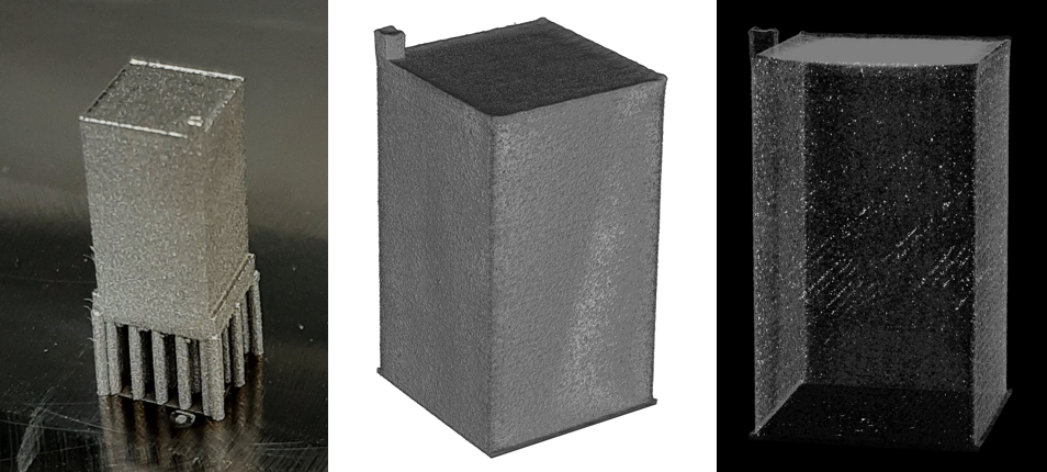
A 3D-printed metal object (left), a 3D visualisation of the edges of the object from a CT reconstruction (centre), and a 3D visualisation of internal defects inside the object (right).
Technologies for 3D imaging
Stereo vision
A popular method of 3D imaging is based on stereovision. This works in the same way as depth vision in humans: the scene is observed with two cameras (or eyes) from two different known positions, the corresponding objects are identified with each other, and from the angle information the depth to the object is inferred.
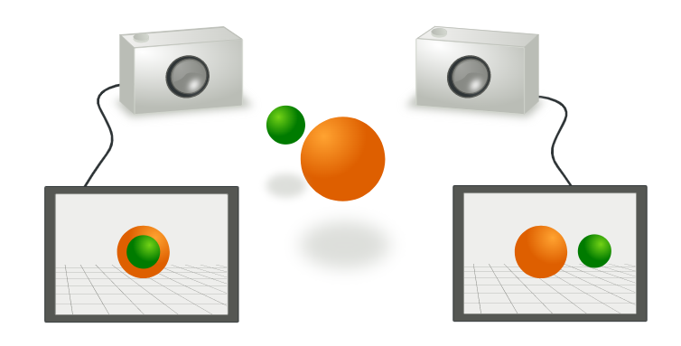
Two cameras observe a scene from different perspectives. From their known geometric arrangement, depth information can then be inferred Arne Nordmann (norro), CC BY-SA https://creativecommons.org/licenses/by-sa/3.0, via Wikimedia Commons.
Stereo images can be interpreted by a human if each eye is shown one of the images. This therefore forms the basis of many 3D vision applications, such as 3D vision in a cinema (based on polarisation or colour filters) or 3D glasses.
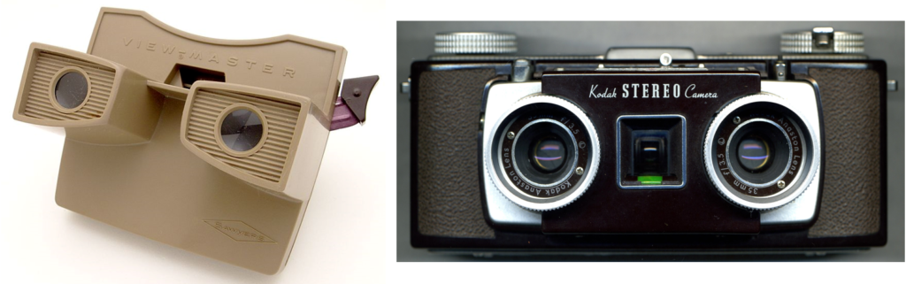
3D vision based on stereo vision has been around for a long time. John Alan Elson, CC BY-SA 4.0 https://creativecommons.org/licenses/by-sa/4.0, via Wikimedia Commons
Getting from a stereo image to a depth image requires several steps, including finding similarities between the same objects, building a "disparity map" that represents the differences (distance in pixels) between objects in the two images, and making the geometric conversion from this disparity to depth. Modern stereo cameras contain the necessary algorithms to calculate this on the device, and will therefore give a depth image as output. Most image processing platforms also have algorithms to determine a depth map from a known geometry and two images (see, for example, this solution in OpenCV)
A special case of stereo vision are one-dimensional distance sensors based on triangulation: A light point is projected onto the object and observed from a short distance with a single row of light-sensitive cells (a CCD line sensor). From the angle, a one-way distance can then be quickly determined. Such sensors find many uses as very cheap but relatively inaccurate distance sensors, for example in drones (e.g. ground detection), automation (e.g. checking presence of a box) and home automation (automatic taps, toilets, doors, soap dispensers, ...).
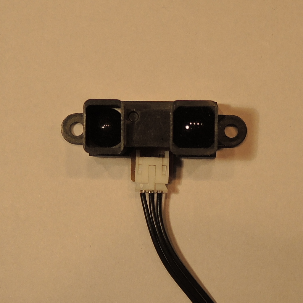
A Sharp GP2Y0A02YK infrared distance sensor. One eyelet contains an IR diode that projects a light point. The other eyelet contains a small CCD line sensor. The internal electronics convert this to a distance, in the form of an (analogue or digital) signal. Stefan Tauner, CC BY-SA 3.0 https://creativecommons.org/licenses/by-sa/3.0, via Wikimedia Commons
LIDAR
LIDAR stands for "light detection and ranging", and is also called laser scanning, laser rangefinder or 3D scanning. This technology is similar to echolocation, but with light: A very short pulse of light is emitted in a certain direction, and the time to detect the reflection (the "echo" of the light) is accurately measured. Since the speed of light is constant, the distance can then be determined from this. This technique is therefore called "time of flight".
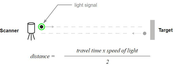
Het "time of flight" concept van een LidAR. Cartographer3D, CC BY-SA-4.0 https://creativecommons.org/licenses/by-sa/4.0, via Wikimedia Commons
The light source in LIDARs is usually an (infrared) laser, for several reasons: Laser light is collimated and thus easy to focus in a thin beam. Furthermore, it is also monochrome, which causes less dispersion (spatial spread) of the light pulse, and laser diodes are cheap and easy to control. The accuracy of a LIDAR is related to the accuracy of its internal timer, and picosecond accuracy is no exception. This leads to millimetre-accuracy. However, the observed surface must reflect the laser light used: Surfaces that absorb ("black out" the IR light used) or reflect (mirror) the light elsewhere are therefore poorly observable or invisible to a LIDAR.
LIDARs can be one- to three-dimensional:
- 1-dimensional: The device measures the distance to 1 point. Think, for example, of non-contact distance meters popular in construction.
- 2-dimensional: The device measures all distances over 1 (horizontal) plane or over 1 line, for example by using a single rotating mirror, a diffraction element or a MEMS mirror. This is also called a line scanner, and finds use in rolling-band systems to scan passing objects, and in e.g. (expensive) robotic hoovers to detect obstacles.
- 3-dimensional: The device builds a full 3D point cloud (a depth map from the scanner's perspective). Accurate 2-mirror scanning systems are often used for this purpose to focus the laser, combined with high-performance and fast processing that allows millions of scan points per second.
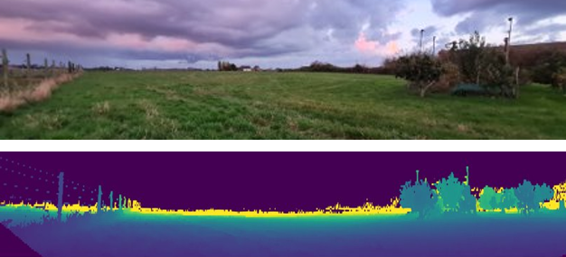
A 3D LIDAR depth map (bottom) of an agriculture scene (top).
LIDARs come in different quality classes and models, ranging from hand-held 1D devices to very expensive and sophisticated 3D LIDARS that can take millions of measurements per second with high accuracy in both angle and distance. The distances over which LIDARs operate also vary widely: from a few metres for simple consumer LIDARS to planetary distances.
ToF camera
Another category of 3D distance sensors based on the same time of flight (ToF) technology are ToF cameras. Here, a short light pulse or pattern is emitted from a diode or a flash lamp that will illuminate an entire scene at once. This wavefront will reach different objects at different times depending on their distance. Then, a special 2D (CCD or CMOS) sensor will determine the time for each pixel to perceive this reflected light front. In this way, a complete depth map can be built in one operation.
The performance of a ToF camera varies greatly with price and quality: accuracy is typically on the order of a few millimetres to centimetres, maximum distances of a few to tens of metres, resolutions of hundreds to tens of thousands of points, and refresh rates in the 1-100 Hertz range. Prices range from 100 euros for the simplest models to thousands of euros for the high-performance ones. Note that this puts us in the same price range and performance as LIDAR sensors.
Applications of ToF cameras are very broad: people detection (blind spot camera, automatic escalator start, door opening, ...), people counting (crowd control, building access, passengers in a vehicle, ...), object detection and (shape) classification, collision avoidance, path planning, ... These sensors now also find application in some more expensive smartphones to build a depth map of a scene to simplify focus, exposure and depth effects of photography. The popular Kinect (version 2) also uses a ToF camera to build a depth image.
Note that acoustic time-of-flight sensors also exist, where a "chirp", or ultrasonic sound pulse, is emitted and its echo is detected through a filtered microphone. These sensors perceive objects in a relatively wide cone in the viewing direction, and are thus ideally suited for simple distance and security applications (e.g. parking sensors in vehicles).
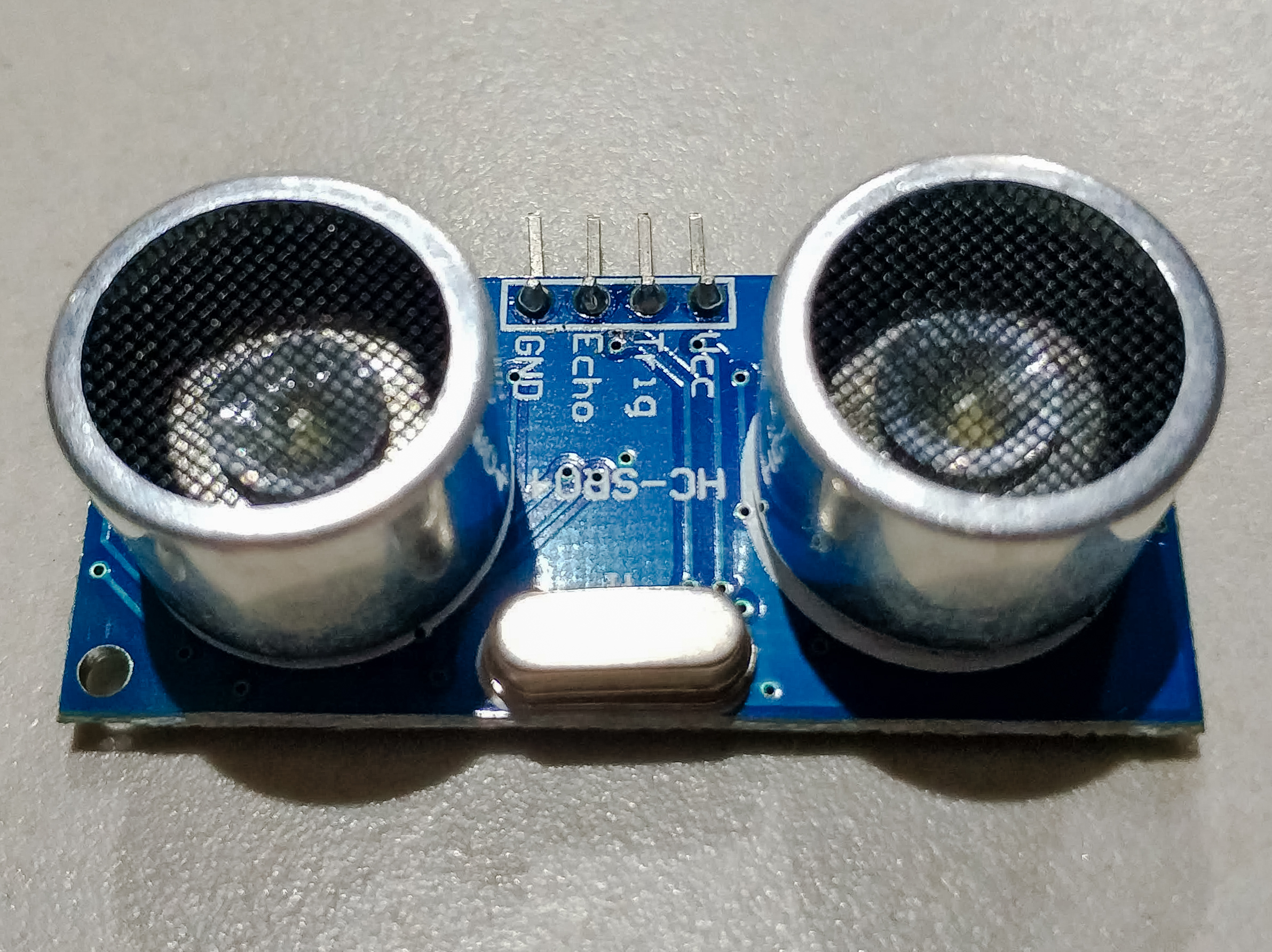
An ultrasonic distance sensor, with separate emitter and receiver. Models that integrate both also exist, and are very popular as distance sensors in vehicles. Nowforever, CC BY-SA 4.0 https://creativecommons.org/licenses/by-sa/4.0, via Wikimedia Commons