Introduction to industrial cameras

Introduction to industrial cameras
When putting together a machine vision system, the choice of camera and lens depends on several factors such as the objects to be detected, the desired output, available light, temperature, available space, and, of course, the price of the complete system. This article contains a brief description of the different aspects of an industrial camera, and references to more information for the interested reader. This will allow you to select the type of sensors that fit the needs of your application.
Area scan and linescan sensors
The sensor in an industrial camera can take different shapes, depending on its function. The most common are rectangular sensors that can register 2D images (area scan) and line-shaped sensors for 1D images (line scan). Which one is preferable depends very much on the situation:
- Area scan sensors are capable of perceiving an entire image at once, and are thus suitable for remote monitoring of static or dynamic situations. Examples include pick-and-place applications, remote monitoring of systems, locating or tracking an object, and quality control.
- Line scan or line scan sensors are ideally suited to situations where there is an intrinsic constant motion, such as conveyor belts, product flows or moving platforms (car, aircraft, satellite, ...). The motion itself will form the 2nd spatial dimension of the image, which allows a line scanner to build up a basically infinitely long 2D image continuously. Using an area scan sensor for such a situation would present a lot of difficulties due to the large overlap between successive images and the need for synchronisation and stitching. Another way of looking at a line scan sensor is as a spatio-temporal sensor, where the 2nd spatial dimension is a linear function of time.
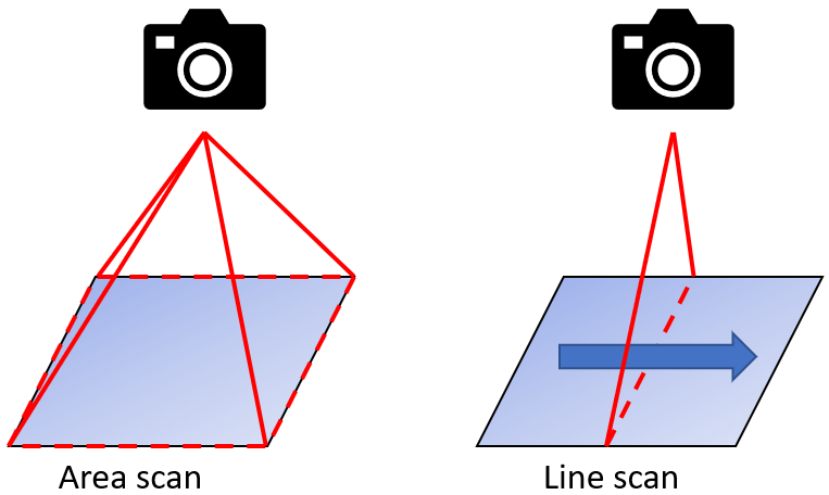
An area scan sensor (left) perceives a rectangular 2D image, a line scan sensor (right) a single 1D line. Due to the movement of the object, a line scan sensor can still build up a 2D image, line by line.
Geometry of a sensor
The geometry of a standard area scan sensor already determines many of its properties. For example, a sensor has a physical size, traditionally expressed as a ratio and a length:
- The "size" of a sensor is the diagonal distance measured between two opposite points of the rectangle. This distance is given in mm or in inches (1 inch = 25.4mm).
- The ratio between the long (horizontal) and short (vertical) sides of the rectangle is the sensor's aspect ratio. The most common aspect ratio is 4/3, although there are very many deviations from this. Also, this is not always a nice ratio due to electronic or digital trade-offs.
If the diagonal and aspect ratio of the rectangle are known, the horizontal and vertical length can be determined unambiguously.
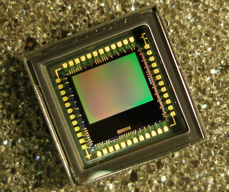
A standard image sensor on a chip. The light-sensitive sensor array itself is the green-red tinted rectangle in the centre. Filya1, CC BY-SA 3.0 https://creativecommons.org/licenses/by-sa/3.0, via Wikimedia Commons
A sensor consists of a regular grid of light-sensitive cells called pixels. The number of rows and columns of pixels in this grid is the resolution of the sensor, and is often represented as two numbers. The total number of pixels is then the product of these two numbers, and is often given in megapixels (1 million pixels). In almost all cases, pixels are square, and so the ratio of the two resolution numbers will correspond to the physical aspect ratio of the sensor. The physical size of the sensor and its resolution also determine the size of an individual pixel, the "pixel pitch". Note that the effective photosensitive area of a pixel is usually smaller than its full theoretical size: The ratio of the two is called the "fill factor", or filling factor. We give an example for clarification using the Sony IMX007 sensor:
- The image sensor has square pixels, with a resolution of 4312 x 2880. This means there are 2880 horizontal rows of pixels and 4312 vertical columns in sensor array. The total number of pixels is 12418560, so this is a 12.4 MP (megapixel) sensor.
- The aspect ratio can be calculated from this as 4312 / 2880 = 1.497. So this is (almost) a 3/2 ratio.
- The sensor has a size of 28.47mm. With the known aspect ratio, this can be converted into the horizontal x vertical dimensions 23.67 x 15.81mm.
- From this, the size of 1 pixel can also be calculated: Each pixel is 5.49 x 5.49 μm, or the pixel pitch is 5.49 μm
Apart from technical limitations, there is basically no limit on the number of pixels one can place on a sensor, but some physical and practical limitations do start to come into play:
- A larger pixel will receive more light, resulting in a better signal-to-noise ratio and better performance in dark environments.
- A smaller pixel allows more pixels to be placed on the sensor and thus theoretically more details to be observed. However, a lower limit is imposed by the optical characteristics of the lens system: The modulation transfer function of the lens determines (roughly) the smallest details that are still sharply visible on the sensor, and if the pixels become smaller than this level it will only result in blurred details, without adding extra info. There are also mechanical and electronic limitations, so the smallest possible pixel pitch is currently around 1 μm. Typical sensors have a pixel pitch around 3 - 10 μm.
- High resolution with a large pixel pitch gives a sharp image with little noise, but results in a physically large (and expensive) sensor which also needs large (and expensive) lenses. Trade-offs must always be made here.
A line scan sensor, unlike an area scan sensor, has only 1 dimension. Most of the above concepts still apply to a line scan sensor, where the vertical resolution is a small number corresponding to one or a few rows of pixels.
Monochrome, colour and spectral cameras
An area scan sensor is always limited to observing a single signal per pixel, which will therefore produce an intrinsically monochromatic image. However, applying per-pixel filters and interpolation still allows multiple colour channels to be observed with a single sensor. For traditional colour cameras based on three channels (RGB), this is typically achieved via a Bayer filter matrix, where each pixel has a colour filter (red, green or blue). Half the pixels have a green, a quarter a red and the rest a blue filter. More pixels have a green filter to mimic human perception, which is known to be more sensitive to the green light. To determine the final 3-channel colour of each pixel, information from adjacent pixels is used by the debaying algorithm. Most conventional colour sensors available on the market today have this process of debaying embedded, allowing the three-channel (RGB) colour image to be obtained directly from the sensor itself.
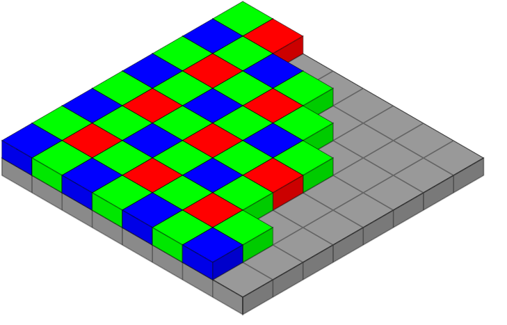
Een Bayer filter bovenop een area scan sensor. en:User:Cburnett, CC BY-SA 3.0 http://creativecommons.org/licenses/by-sa/3.0/, via Wikimedia Commons
If the intended application does not require colour information for analysis, it is best to use a monochrome camera. These sensors are more sensitive than colour cameras (no filters, and therefore more light and a larger signal) and provide more detailed images. Also, RGB cameras are optimised for visual display to people, which is often secondary to the application in an industrial scenario. On the other hand, one can also change the Bayer patterns on a sensor, e.g. to perceive other wavelengths, or expand further to more than 3 channels, e.g. like the imec multispectral snapshot sensors which can perceive 16 to 25 colour channels. The compromise for the higher spectral information of such spectral snapshot sensors is the larger interpolation artefacts. https://www.imechyperspectral.com/en
Line scan sensors have an additional advantage in this respect: the missing second spatial dimension can be used to split incoming light into different spectra (e.g. with a prism or a diffraction grating), thus obtaining a spatial-spectral signal (multispectral or hyperspectral imaging). No interpolation is required here, and the number of colour channels per pixel can be large, in the order of dozens (multispectral), hundreds (hyperspectral) to thousands (ultraspectral) of channels. Note that a lot of alternative imaging techniques exist to generate spectral images, based on geometrically spreading the colour info with a dispersion element, selective filtering of wavelengths or selective illumination with monochrome light sources.
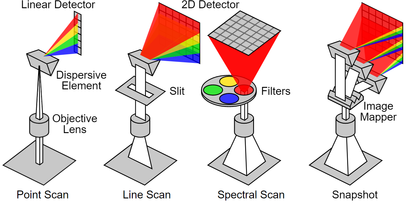
Different spectral imaging techniques. Lucasbosch, CC BY-SA 4.0 https://creativecommons.org/licenses/by-sa/4.0, via Wikimedia Commons
Spectral images provide extremely large amounts of colour information in each pixel, and advanced hyperspectral systems even allow recording a detailed spectrum per pixel, well beyond the visible region (UV - VIS - NIR - SWIR - MIR - LWIR - TIR). However, this comes at the cost of their high noise sensitivity (little light per pixel per colour channel), their complex structure (large, cooling required, large bandwidth, delicate sensors, ...) and their very high price (tens of thousands of euros for VIS-NIR, up to hundreds of thousands for SWIR).
We do not wish to go deeply into spectral imaging in this article, but we have a lot of experience in this. Feel free to contact us if you would like more info on this.
Sensor technology: CMOS, CCD and alternatives
In CMOS (Complementary Metal-Oxide Semiconductor) cameras, the electronics that convert light into digital signals are integrated into the surface of the sensor (e.g. amplifiers, noise correction and digitising circuits). This makes the transmission of the digital data particularly fast. CMOS sensors are less expensive, show no outflow or speckle, and have a higher dynamic range. In the automotive industry, this last feature is quite important as it allows capturing both an illuminated number plate and the shadow person in a car in the same image.
Charge-coupled device (CCD) sensors have no conversion electronics on the sensor surface. When light enters the photoreceptor, it is stored as an electrical charge in the sensor, then converted to voltage, buffered and transmitted as an analogue signal when the shutter is closed. They can capture more light and thus have lower noise factor, high fill factor and higher colour fidelity. These features make CCD cameras a good choice for low-light, low-speed applications such as astronomy.
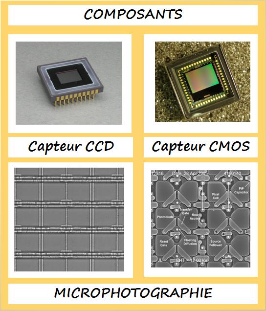
A CCD and CMOS sensor, with microscopy images clearly showing the higher complexity of the CMOS sensor. Master dpo, CC BY-SA 3.0 https://creativecommons.org/licenses/by-sa/3.0, via Wikimedia Commons
The substrate of the sensor itself determines the wavelengths to which the sensor is sensitive, and often the price. The spectral response curve of a substrate shows its efficiency to convert photons into an electrical charge as a function of wavelength, and hence how sensitive the sensor is to light of a particular wavelength or colour. A good response in the area to be observed is obviously indispensable.
For visible light, silicon substrates are very suitable. This technology is also relatively cheap. Quasi all commercial cameras for visible light are based on silicon technology. Note that silicon is also very sensitive to near-infrared light, and NIR cameras can easily be made with Si-based sensors. For use only in the visible region, however, this sensitivity is undesirable, and in practice a shortpass filter is placed in front of the sensor which does not let the NIR wavelengths through.
For infrared light of longer wavelengths, other technologies are needed. InGaAs sensors are very sensitive in the SWIR region, for even longer wavelengths one can turn to HgCdTe or Vanadium oxide technologies. Due to the need for cooling, sensitive and complex construction and low production volumes of these sensors, they are very expensive to buy.
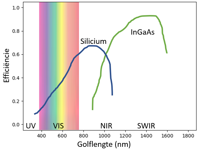
The spectral response curve for two different substrates: Silicon (the "standard" sensor, often used for visible light and near infrared) and Indium-Gallium-Arsenide for short-wave infrared.
Framerate and shuttertime
The frame rate of a sensor or camera is the number of images that can be captured per second, and is expressed in frames per second (fps), or images per second. The frame rate of a film is usually 24 fps. From about 14 to 16 fps, a film played back looks smooth to the human brain.
In industrial applications, however, much higher frame rates may be required. Monitoring systems for high-speed processes such as, for example, welding arc monitoring, laser monitoring in selective melting for 3D printing, or free-fall sorting machines easily achieve frame rates of several thousand frames per second. Note that this is often at the expense of resolution: The amount of data generated by a sensor is roughly proportional to the number of pixels recorded per second. This, in turn, is proportional to the resolution of each frame, and to the number of frames per second recorded. Given that the speed at which data can be streamed to peripherals is limited by the hardware providing the communication, higher frame rates will require lower resolutions.
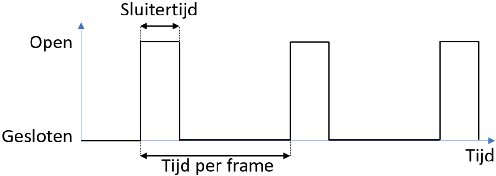
The signal that opens and closes the sensor's shutter as a function of time. The shutter speed is the period the sensor is sensitive to light during each period, the frame rate the inverse of the time per frame.
The shutter speed of a camera is the time interval during which the sensor is "open" to record a single video frame. This is also called the integration time. During the opening of the shutter, the sensor is sensitive to incoming light, and incoming photons are collected in each sensor element and converted into an electrical signal (a charge or a voltage). The longer the shutter speed, the more light is collected and the better the signal-to-noise ratio will become. This is especially important in darker situations. However, long shutter speeds come at the expense of "motion blur", blurring of the image caused by the movement of the subject during the time the shutter is open. Slow shutter speeds give sharper images without motion blur, which is especially important in fast processes. This then comes at the expense of the signal-to-noise ratio, and will produce dark choppy images. A correct and powerful exposure, or stroboscopic exposure synchronised with the opening of the shutter can provide a solution here.
Shutter speeds are limited by the camera's frame rate (the shutter cannot be open longer than the time between two frame shots) on the one hand, and the digital and electronic limitations of the sensor that impose a minimum shutter speed on the other. Note that most sensors require a short time for the sensor to read and reset after shooting each frame, so a minimum period during which the shutter is closed is necessary.
Global and rolling shutter
Shutters in digital photography are electronic, and incorporated into the sensor hardware. However, the way a shutter then works and reads the sensor can differ between technologies. The two most common types are the global and rolling shutter.
If you want to avoid distortions at high speeds and are not too worried about price, especially if you have a dynamic process/system, then a global shutter sensor is the optimal choice. With the global shutter, the entire sensor surface is exposed to light at the same time. It is great for high-speed applications, such as traffic and transport, or logistics.
A rolling shutter reads an image line by line and the lines are then recomposed into a single image. If the object is moving fast or lighting conditions are poor, the image will be distorted. However, there is a solution to minimise the distortion effects by adjusting the exposure time of the sensor and adding a torch to the system.
In general, a global shutter is more difficult to construct and therefore more expensive. However, for industrial applications, it is usually the best choice.
A global shutter registers the entire image at once. Events between two registrations can therefore be missed. A rolling shutter registers line by line, allowing the object to move between successive lines. Jacopo Bertolotti, CC0, via Wikimedia Commons